- #Analog to digital converter microcontroller full#
- #Analog to digital converter microcontroller code#
- #Analog to digital converter microcontroller free#
The ratio of the fundamental frequency's amplitude to that of the largest spurious signal in a given bandwidth.

INL produces additional harmonics and spurs in the frequency domain.
#Analog to digital converter microcontroller full#
The difference between the ideal and actual output when the converter input is at full scale. Gain error/full-scale error, expressed in terms of LSB The difference between the ideal and actual output when the converter input is zero.Ĭalculated after offset and gain errors are removed.
#Analog to digital converter microcontroller code#
The narrowing or widening of code widths caused by DNL can lead to “missing codes” and add noise and frequency spurs beyond the effects of quantization. The deviation of an actual code transition point from its ideal position on a straight line drawn between the end points of the transfer function. Integral nonlinearity (INL), expressed in terms of LSB


In an ideal converter, every code is exactly the same size and DNL is zero.ĭNL, INL, offset error, and gain error specify how accurately the data represents the signal across the entire internal and external range. The deviation from the ideal (1 LSB) code width between any two adjacent codes. LSB size is a function of converter resolution.ĭifferential nonlinearity (DNL), expressed in terms of LSB The right-most bit in an ADC output code. The number of repetitive conversions per second for a full-scale change to specified resolution and linearityĭetermines the fastest sampling capability of the ADC Number of bits representing an analog signal, generally ranging from 6 to 24.ĭetermines how small an input can be resolved.Ĭonversion speed or rate, ksamples/s or Msamples/s Don’t expect to get accurate measurements unless you do it properly (which is too much to explain here).Specification and terms, units of measure Then you know voltage and resistance and can calculate power. If you really want to measure power you can for example measure the resistance of the LDR using a multimeter under different lighting conditions and under those same conditions you measure your analog input value from a voltage divider. LDRs don’t generate current by themselves! See To measure the current you would need a circuit that converts the current into voltage and amplifies it suitably. You would need a voltage divider or other circuit. To measure a varying voltage due to the LDR, google for example Arduino LDR. The analog pins only measure voltage relative to the reference voltage, not current. The short answer is: No, you don’t want to do that. LCDWriteIntXY( 4, 1,adc_result, 4) //Print the value in 4th column second line The code writes '1' but it result in setting bit to '0' !!!Īdc_result=ReadADC( 0) // Read Analog value from channel-0 Clear ADIF by writing one to it //Note you may be wondering why we have write one to clear it //This is standard way of clearing bits in io as said in datasheets. Wait for conversion to complete while(!(ADCSRA & ( 1<

SystemĬlock can be divided by 2,4,16,32,64,128 by setting the Prescaler. Produces acceptable frequency for ADC from any system clock frequency. As the system frequency canīe set to any value by the user (using internal or externals oscillators)( In Lower frequency the conversion is more accurate. At higher frequency the conversion is fast while a The ADC requires a frequencyīetween 50KHz to 200KHz. This clock generated by systemĬlock by dividing it to get smaller frequency. The ADC needs a clock pulse to do its conversion. It does a conversion and then start nextĬonversion immediately after that. While inįree it is continuously converting. In single conversion mode the ADC does the conversion and then stop.
#Analog to digital converter microcontroller free#
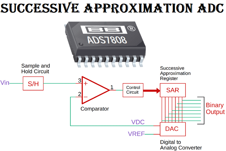
The ADC can be operated in single conversion and free running more. The ADC is multiplexed with PORTA that means the ADC channels are shared Now you know the basics of ADC let us see how we can use the inbuilt ADC ofĪVR MCU.


 0 kommentar(er)
